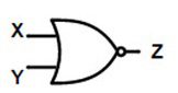
NOR Gate Logic Symbol
Below figure shows the NOR gate logic symbol
Mathematical expression for NAND gate operation is given as Z =(X+Y) ̅.Where, bar “ ̅“represents the reverse operation.
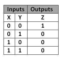
NOR Gate Truth table
Below is NOR gate truth table. It shows that NOR gate outputs logic high value if both the inputs are at low logic level. This produces logic low value if any of its inputs is in high logic level. Back to top
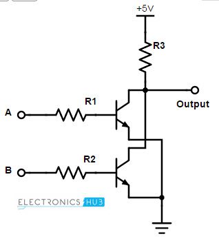
2-Input Transistor NOR Gate
In two input NOR gate two transistors are used to design a NOR gate. A circuit driving voltage of +6 volts is connected to the collector of first transistor.The same supply voltage will be parallelly connected to the collector of second transistor also. Connect two resistors as the inputs of NOR gate (each of 10K). The emitters of two transistors are collectively connected to ground. The output is collected at the node of supply voltage , resistor and collector of first transistor. The 2-input NOR logic gate designed by using two transistors is shown below.
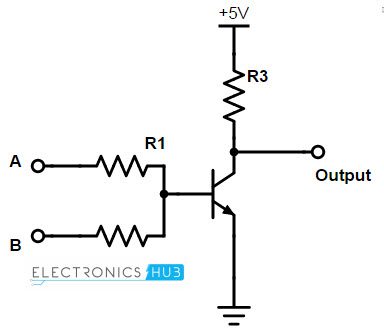
There is another design method available for NOR gate i.e. single transistor designed NOR gate. Here, the base of the transistor is supplies with parallelly connected two inputs, through resistors. The emitter is connected to ground and the collector is connected to the circuit driving voltage (supply voltage) of +6 Volts. Output is collected at the collector end of the transistor. Observe the below diagram.
This is an alternative way of achieving NOR logic gate.
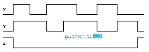
Pulsed operation
If we apply 2 different clock signals as the inputs of NOR gate X and Y, then the output of the NOR gate will be as shown below (X, Y are inputs and Z is output)
If we observe the above clock signals, we can say that when both inputs are high, then the output of the NOR gate is LOW and the LOW output state continued for every input logic low level. At the end of the clock pulses, the output becomes high as both the inputs of NOR gate the inputs are low. Back to top
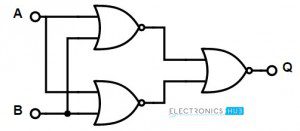
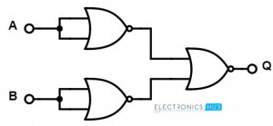
Universal NOR Gate
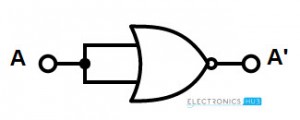
NOR logic gate is called as the “Universal logic gate”. This gate can function as any of the basic logic gates by just making some changes at its input side. Mostly, we prefer NAND gates over NOR gates for designing the other basic logic gates. Let’s see how we can design other gates by using NOR gate. Basic Logic Gates using only NOR Gates We can design basic logic gates such as AND, OR, NOT gates. Let’s see how a NOR gate can perform all the 3 types of functioning.
Back to top
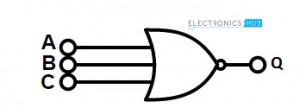
3 -Input NOR gate
Multi input NOR gate can be designed by connecting other logic gates at its input side. Let’s see the logic symbol and truth table of 3 –input NOR gate. There is no change in Boolean expression with change in number of inputs. The output of NOR gate is the inverse of addition of NOR inputs. 3-Input NOR gate symbol The Boolean expression for the 3-input NOR gate is Q = (A+B+C) ̅
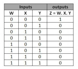
Truth Table
The truth table of 3 –input NOR gate is given below
The output of the 3 input NOR gate is LOW when all the 3 inputs are HIGH and it will be HIGH for all other combinations of inputs. Back to top
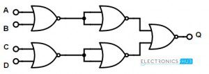
4-Input NOR gate
Similar to 3-input NOR gates, we can also design 4-input NOR gate.
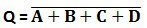
Its Boolean expression is Back to top
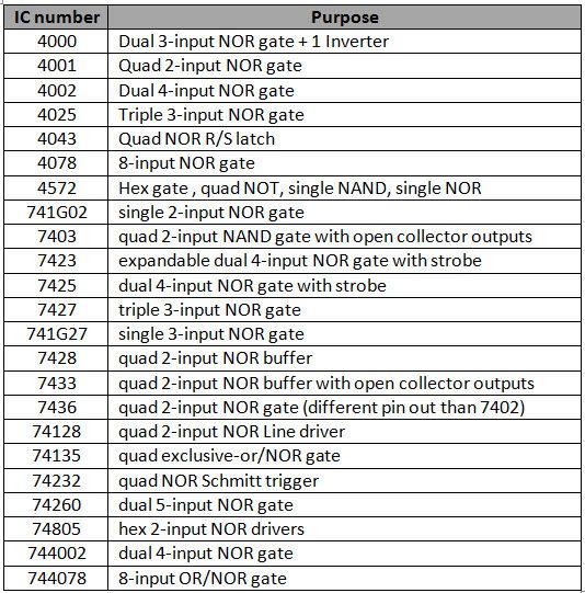
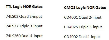
Commonly available TTL and CMOS logic NOR gate IC’s
List of ICs of all TTL and CMOS logic NOR gates are given below
Some of the most used NOR gate ICs are
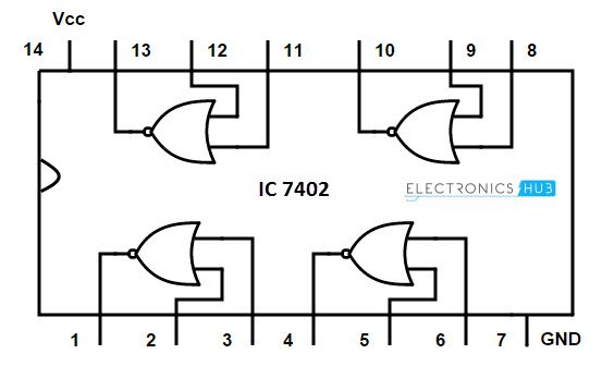
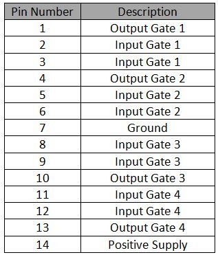
7402 Quad 2-input NOR Gate IC
Back to top
NOR Gate Applications
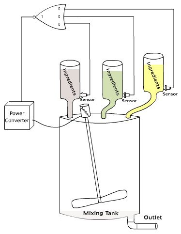
Logic NOR gate can be used to construct EX-OR gates and some other real time applications. One of its real time applications is ‘Mixer tank’. It is explained below. If you observe the below diagram, we use a 3-input NOR gate to control the flow of ingredients of a mixer tank. Different kinds of ingredients are stored in separate cylindrical Hooper. A capacitive proximity switch is arranged outside of each cylinder, at its bottom. This is to detect the amount or level of ingredient.
When the ingredients come down to the sensor level, the cylinder produces HIGH level logic output. The ingredient level higher than the sensor will consider as low logic level (0).When all the ingredients comes down to the sensor level, then all inputs of the NOR gate will become HIGH. When all the ingredients comes down to the sensor level, the output of NOR gate will become HIGH. This output is connected to the Power converter and this power converter is connected to the Motot (to mix the ingredients). The HIGH output of the NOR logic gate activates the power converter and activates the motor, making the motor to run and mix all the ingredients. Back to top Comment * Name * Email * Website
Δ
![]()
![]()
![]()
![]()
![]()

