A Brief Note on Temperature Controlled Switch
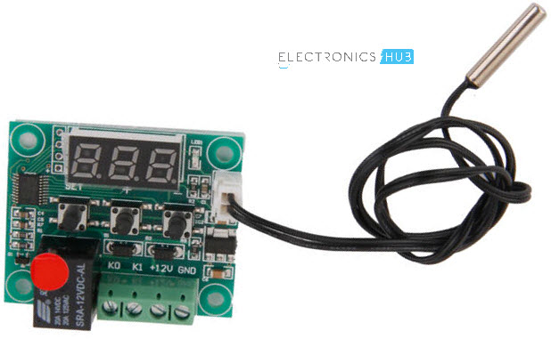
As the name suggests, a Temperature Controlled Switch is a device or circuit, which is activated based on the Temperature. Any Temperature Controlled Switch consists of three parts: Sensor, main control unit and the switch. The following image shows a commercially available Temperature Controlled Switch. It contains of a sensor connected through a wire, a main controller, a display system and the switch.
How does a Temperature Controlled Switch work?
All the three components i.e. the Temperature Sensor, the Controller and the Switch play equally important roles in the working of any Temperature Controlled Switch. First, the Temperature Sensor reads or senses the temperature and transmits this data to the controller. The data received by the controller is then processed and the controller produces an appropriate output signal to the switch. Upon receiving the signal from the controller, the switch is either tuned ON or OFF. This process repeats forever.
Implementing a Temperature Controlled Switch
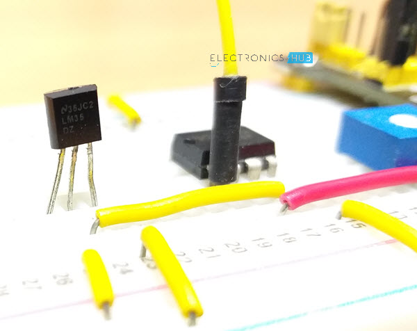
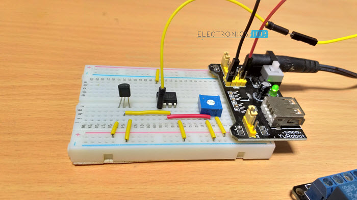
In this project, I am not going to design a commercial type Temperature Controlled Switch as shown above but rather a simple one with components that are easily available and a simple design so that interested people can implement this project as a DIY Project. Now coming to the components, I have chosen LM35 as the Temperature Sensor, LM358 Op Amp as the main control unit and a Relay Module as the Switch.
Circuit Diagram of Temperature Controlled Switch
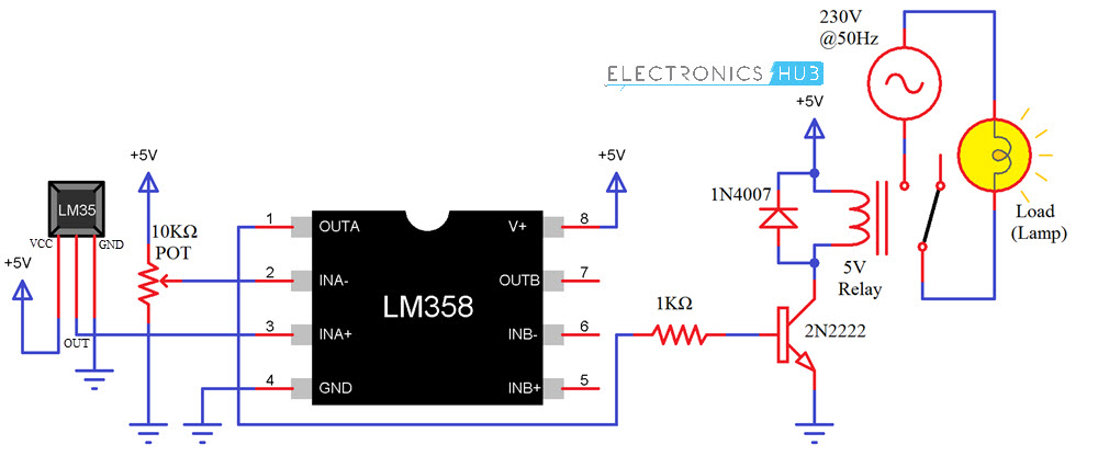
The following image shows the circuit diagram of a simple Temperature Controlled Switch using LM35 Temperature Sensor, LM358 Op Amp and a 5V Relay Module.
As you can see, I have used a 5V Relay Module in the project. If you don’t have one, then follow the circuit shown below to implement the relay system with Relay and few other discreet components.
Components Required
LM358 Op Amp LM35 Temperature Sensor IC 5V Relay Module 10KΩ Potentiometer Connecting Wires 5V Power Supply Mini Breadboard
If you don’t have a Relay Module, you can make one yourself easily using the following components:
1KΩ Resistor NPN Transistor (like 2N2222 or BC547) 1N4007 PN Junction Diode 5V Relay
Circuit Design
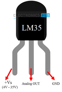
Let me start describing the design of the Temperature Control Switch circuit with the Op Amp LM358. Pins 8 and 4 (V+ and GND) of LM358 are connected to +5V and GND. Since, LM358 is a dual op amp IC, you can use either of the Op Amps. Pins 1, 2 and 3 are associated with one ap amp and pins 5, 6 and 7 with the other. I will be using the first op amp i.e. pins 1 (OUT), 2 (INA-) and 3 (INA+). Now, connect the wiper terminal of the 10KΩ Potentiometer to Pin 2 of LM358 (the other terminals of the POT are connected to +5V and GND). Pin 3 of LM358 is connected to the OUT Pin of LM35 Temperature Sensor. The other two pins of the LM35 IC are connected to +5V and GND. The following image shows the Pins of LM35 Temperature Sensor IC in its TO-92 Package.
Coming to the output of the Op Amp, the Pin 1 is connected to the IN pin of the Relay Module. The VCC and GND pins of the relay module are connected to +5V and GND. I did not connect any load to the relay but you can connect any load like a light bulb for example, in series with mains supply across NO and COMM terminals of the relay. WARNING: If you want to use the relay and control an electrical load, please be extremely careful when making the connections with AC Mains supply.
Working
The working of this Temperature Controlled Switch circuit is very simple. First, let me begin the discussion with LM358 Op Amp. In this circuit, it is configured as a Comparator i.e. it compares the voltage levels at Pins 2 and 3 and produces a relevant output.
Pin 3 (IN+) of the Op Amp is the non-inverting input and is connected to OUT of the LM35 Temperature Sensor. Pin 2 (IN-) on the other hand, which is the inverting input, is connected to a voltage divider i.e. a Potentiometer. Under normal condition, the inverting input will be greater than the non-inverting input and as a result, the output of the Op Amp is LOW. Since this output is connected to the Relay, it stays turned OFF. When the temperature increases, the output of the LM35 Temperature Sensor increases as a rate of 10mV/0C. If the temperature reaches a certain threshold, the non-inverting input of the Op Amp becomes higher than that of the non-inverting input and as a result, the output of the Op Amp LM358 becomes HIGH. This in turn will turn ON the relay.
Applications
HVAC Systems Power Supplies Water Tanks Freezers Battery Management Systems Industrial Applications like Boilers, steamers, chillers etc.
Comment * Name * Email * Website
Δ
![]()
![]()
![]()

![]()
![]()

