Two resistors are said to be in series when same current flows through them. Resistors in series can be replaced by a single resistor. All the resistors follow the basic laws like Ohm’s law and Kirchhoff’s current law irrespective of their combination and complexity.
Resistors in Series
A set of resistors are said to be in series when they are connected back to back in a single line. The same current will flow through all the resistors. Resistors in series are said to have common current.
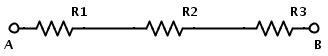
In a series resistor network, the amount of current that flows will be same at all points. IR1 = IR2 = IR3 = IAB. Consider the following series resistive circuit
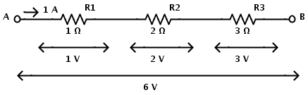
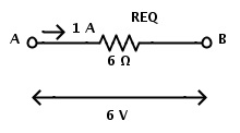
Here the resistors R1, R2 and R3 each valued 1 Ω, 2 Ω and 3 Ω are in series connection. Same current will flow through all the resistors since they are connected in series. The total resistance of the circuit is equal to sum of individual resistances. If RT is the total resistance, then RT = R1 +R2 +R3 Now the equivalent resistance of the circuit is REQ = R1 + R2 +R3 REQ = 1 Ω + 2 Ω + 3 Ω REQ = 6 Ω Now the resistors in series combination can be replaced by a single resistor REQ of the value 6 Ω.
Equivalent Resistance Formula
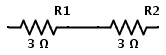
In a series resistor network, the total resistance is equal to the sum of individual resistances as same current passes through each resistor. ∴ RTOTAL = R1 + R2 + R3 For example consider two resistors connected in series as shown below
The combination of two 3 Ω resistors in series is equivalent to having a single 6 Ω resistor. Therefore the above circuit is same as following
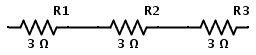
Similarly consider three resistors connected in series as shown below
The combination of three 3 Ω resistors in series is equivalent to having a single 9 Ω resistor. Therefore the above circuit is same as the following
This single resistance is called Equivalent Resistance of the circuit and is used to replace any number resistors in series. If there are n resistors in a series network, then REQ = R1 + R2 + R3 + ……..+ Rn An observation can be made from the above equation. The equivalent resistance of resistors connected in series is always greater than the resistance of largest resistor.
Voltage Calculation
For resistors in series, the voltage across each resistor does not follow the same rule as the current. In case of resistors in series, the total voltage across the resistors is equal to sum of individual potential differences across each resistor.
In the above circuit, the potential difference across each resistor can be calculated using Ohm’s Law. The series circuit has a current of 1 A flowing. Then according to Ohm’s law Potential difference across the resistor R1 is I × R1 = 1 × 1 = 1 V. Potential difference across the resistor R2 is I × R2 = 1 × 2 = 2 V. Potential difference across the resistor R3 is I × R3 = 1 × 3 = 3 V. Therefore the total voltage VAB = 1V + 2V+ 3V = 6 V. Consider a series connection of three resistors R1, R2 and R3 with current I flowing through them.
Let the potential drop from A to B be V. This potential drop is sum of individual potential drops across each individual resistor. Then according to Ohm’s law The potential drop across R1 is VR1 = I × R1 The potential drop across R2 is VR2 = I×R2 The potential drop across R3 is VR3 = I×R3 ∴ V = VR1 + VR2 + VR3 ∴V = I × R1 + I × R2 + I × R3 If the equivalent resistance of the resistors connected in series in the above circuit is REQ, then V = I × REQ In case if there are n resistors in series R1, R2….Rn then the total voltage across them is sum of individual potential difference across each resistor. VT = VR1 + VR2 + ….. + VRn In a series resistor combination of n resistors, if the value of resistance of each resistor is different from the other, then the potential across each resistor is different. N resistors in series combination each with different resistance will have N different potential differences across them. This type of circuit will form a Voltage Divider. Voltage divider circuit is the basis of construction of Potentiometer. In a series circuit, the values of voltage, current or resistance can be calculated using Ohm’s law. The resistors can be interchanged in a series circuit without affecting the total power to each resistor, current or total resistance of the circuit.
Resistors in series examples
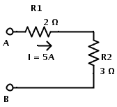
1.Consider the following circuit to calculate total voltage between A and B.
Two resistors R1 and R2 are in series connection. R1 = 2 Ω and R2 = 3 Ω Current in circuit is I = 5 A Individual voltage drops can be calculated using Ohm’s law as follows The voltage drop across the resistor R1 is VR1 = I × R1 = 5 × 2 = 10V The voltage drop across the resistor R2 is VR2 = I × R2 = 5 × 3 = 15V Total voltage drop is sum of individual voltage drops. V = VR1 + VR2 = 10 + 15 = 25V Another approach is by calculating the equivalent resistance of the series combination. The individual resistors in series combination can be replaced by a single resistor of equivalent resistance. The equivalent resistance of two resistors R1 and R2 in series is REQ = R1 + R2 = 2 + 3 = 5Ω Then according to Ohm’s law, Voltage drop across A and B is V = I × REQ = 5 × 5 = 25V.
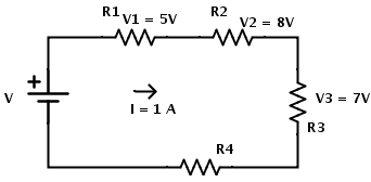
R = 30Ω and I = 1 A The current flowing through each resistor is same. I = I1 = I2 = I3 = I4 = 1 A. According to Ohm’s law the value of resistance can be calculated as R1 = V1 / I1 R1 = 5 / 1 = 5Ω Similarly R2 = V2 / I2 R2 = 8 /1 = 8Ω And R3 = V3 / I3 R3 = 7 / 1 = 7Ω The potential across R4 is not specified. But the value of R4 can be calculated from the value of total resistance or equivalent resistance of the circuit. REQ = R1 + R2 + R3 + R4 ∴ R4 = REQ– (R1 + R2 + R3) R4 = 30 – (5 + 8 + 7) R4 = 10Ω Now the potential across R4 can be calculated as V4 = I4 × R4 ∴V4 = 1 × 10 = 10V The total voltage VAB can be calculated in two methods. First method is using individual potential differences. Total voltage is equal to sum of individual potential differences. VAB = V1 + V2 + V3 + V4 Where V1, V2, V3 and V4 are the potential differences across resistors R1, R2, R3 and R4 respectively. Therefore VAB = 5 + 8 + 7 + 10 VAB = 30 V The second method to calculate total voltage is by using the value of equivalent resistance. Total voltage is equal to product of current and equivalent resistance. The values of total current and equivalent resistance are given as I = 1 A and REQ = 30 Ω. Therefore VAB = I × REQ VAB = 1 × 30 VAB = 30 V
Applications
When two resistors of different resistances are connected in series, the voltage across them is different. This method is the basis for voltage divider circuits. If one resistor in a voltage divider circuit is replaced with a sensor, then the quantity being sensed is converted to an electrical signal which is easily measured. The frequently used sensors are thermistors and light dependent resistors. In thermistor, the resistance varies according to temperature. For example, assumethat thermistor has a resistance of 10 KΩ at a temperature of 250C. The same thermistor can have a resistance of 100 Ω at a temperature of 1000C. Hence the potential drop across the thermistor will be different based on the temperature. This change of resistance according to temperature can be calibrated to find the value of temperature from the potential drop across the thermistor.
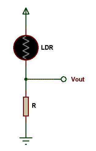
Fig: Light sensor Circuit Another sensor which uses resistor in series combination is Photo Resistor or Light Dependent Resistor. In light dependent resistors, the resistance varies according to the intensity of the light incident on them. In absence of light, the resistance of a typical light dependent resistor is as high as 1 MΩ. In presence of light, the resistance of light dependent resistor drops to a small value generally in the order of few Ohms.This variation in resistance in coordination with light intensity will result in different voltage drops. The voltage drop can be calibrated to find the presence of light of particular wavelength. Comment * Name * Email * Website
Δ
![]()
![]()
![]()


![]()
![]()

