Multiplexer
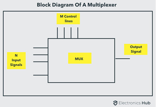
Multiplexer means many into one. A multiplexer is a circuit used to select and route any one of the several input signals to a single output. A simple example of an non-electronic circuit of a multiplexer is a single pole multi-position switch. Multi-position switches are widely used in many electronics circuits. However, circuits that operate at high speed require the multiplexer to be automatically selected. A mechanical switch cannot perform this task efficiently. Therefore, multiplexer is used to perform high speed switching are constructed of electronic components. Multiplexers can handle two type of data i.e., analog and digital. For analog application, multiplexer are built using relays and transistor switches. For digital application, they are built from standard logic gates. The multiplexer used for digital applications, also called digital multiplexer, is a circuit with many input but only one output. By applying control signals (also known as Select Signals), we can steer any input to the output. Some of the common types of multiplexer are 2-to-1, 4-to-1, 8-to-1, 16-to-1 multiplexer. Following figure shows the general idea of a multiplexer with n input signal, m control signals and one output signal.
Understanding 4-to-1 Multiplexer
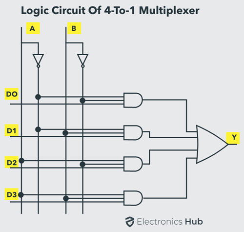
The 4-to-1 multiplexer has 4 input bits, 2 control or select bits, and 1 output bit. The four input bits are D0,D1,D2 and D3. Only one of this is transmitted to the output Y. The output depends on the values of A and B, which are the control inputs. The control input determines which of the input data bit is transmitted to the output. For instance, as shown in figure, when A B = 0 0 , the upper AND gate is enabled, while all other AND gates are disabled. Therefore, data bit D0 is transmitted to the output, giving Y = Do.
If the control input is changed to A B = 1 1 , all gates are disabled except the bottom AND gate. In this case, D3 is transmitted to the output and Y = D3.
An example of 4-to-1 multiplexer is IC 74153 in which the output is same as the input. Another example of 4-to-1 multiplexer is 45352 in which the output is the compliment of the input. Example of 16-to-1 line multiplexer is IC 74150.
Applications of Multiplexer
Multiplexer are used in various fields where multiple data need to be transmitted using a single line. Following are some of the applications of multiplexers – This is just an introduction to the concept of Multiplexer. To learn more about Multiplexers, read this Multiplexer (MUX) and Multiplexing tutorial.
Demultiplexer
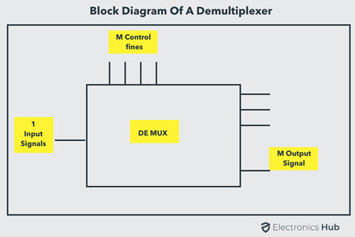
Demultiplexer means one to many. A demultiplexer is a circuit with one input and many outputs. By applying control signal, we can steer any input to the output. Few types of demultiplexer are 1-to 2, 1-to-4, 1-to-8 and 1-to 16 demultiplexer. Following figure illustrate the general idea of a demultiplexer with 1 input signal, m control signals, and n output signals.
Understanding 1-to-4 Demultiplexer
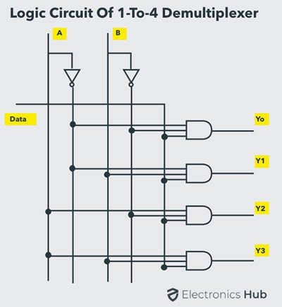
The 1-to-4 demultiplexer has 1 input bit, 2 control or select bits, and 4 output bits. An example of 1-to-4 demultiplexer is IC 74155. The 1-to-4 demultiplexer is shown in figure below-
The input bit is labelled as Data D. This data bit is transmitted to the selected output lines, which depends on the values of A and B, the control or Select Inputs. When A B = 0 1 , the second AND gate from the top is enabled while other AND gates are disabled. Therefore, data bit D is transmitted to the output Y1, giving Y1 = Data. If D is LOW, Y1 is LOW. If D is HIGH, Y1 is HIGH. The value of Y1 depends upon the value of D. All other outputs are in low state. If the control input is changed to A B = 1 0 , all the gates are disabled except the third AND gate from the top. Then, D is transmitted only to the Y2 output, and Y2 = Data. Example of 1-to-16 demultiplexer is IC 74154. It has 1 input bit, 4 control / select bits and 16 output bit.
Applications of Demultiplexer
This is just an introduction to the concept of Demultiplexer. To learn more about Demultiplexers, read this What is Demultiplexer (DEMUX) tutorial.
Conclusion
An introductory tutorial on Multiplexer and Demultiplexer. Learn the basics of Multiplexer, understand a basic 4-to-1 Multiplexer, applications of Multiplexer, Demultiplexer, a basic 1-to-4 Demultiplexer, applications of Demultiplexer. Regards Peter Comment * Name * Email * Website
Δ
![]()
![]()
![]()
![]()
![]()

