In analog voltmeter a pointer moves on the scale to represent the voltage. Digital voltmeter directly displays the voltage in digits with the help of analog to digital converter. This article explains you how to design a digital voltmeter in two methods 1) using 8051 microcontroller and 2)the other using IC L7017.
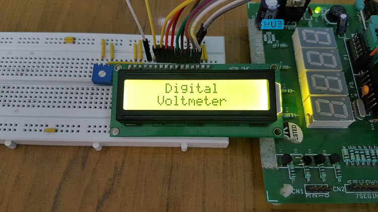
Digital Voltmeter using 8051 Microcontroller
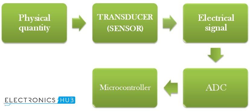
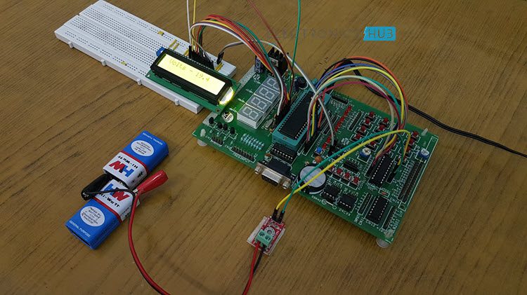
This project measures the input voltage from 0V to 25V. Here, the input voltage should be DC voltage to get the accurate output on LCD. If you apply AC voltage as input, then will see the continuous running numbers on LCD as AC varies continuously. The major components in this project are 8051 microcontroller, a Voltage Sensor Module and an ADC IC ADC0804. In this project, we use analog to digital conversion process to display the voltage. Analog to Digital Conversion In real world, mostly we find analog data. To manipulate this data using digital systems, we need to convert analog data to digital, so that microprocessor or microcontroller is able understand and manipulate the data. Here ADC IC generates the output digital value based on the input electrical voltage. The 8051 microcontroller reads this digital value and displays it on LCD.
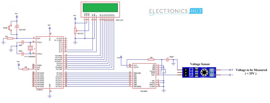
Digital Voltmeter using 8051 Microcontroller Circuit Diagram
Circuit Components
AT89C51 micro controller ADC0804 IC 25V Voltage Sensor AT89C51 programming board Variable resistor (to demonstrate the program) DC Adapter or Battery
Digital Voltmeter Circuit Design using 8051 Microcontroller
In the above circuit, analog to digital converter IC data bits are connected to the PORT2. LCD data pins are connected to the POTR3 of controller and control pins RS and EN are connected to the P1.6 and P1.7 respectively. ADC0804 This is an 8 bit analog to digital converter. This IC uses successive approximation method to convert analog values to digital. It can take only one analog data as input. The step size of this IC is varied by varying the reference voltage at pin9. If this pin is not connected, VCC will be the reference voltage. For every 19.53mV, rise in input voltage the output is incremented by 1 value when the step size is at 5V. The conversion time of this IC depends on clock source. ADC Features
0 to 5V analog input voltage. Built in clock generator. Differential analog inputs. Adjustable reference voltage.
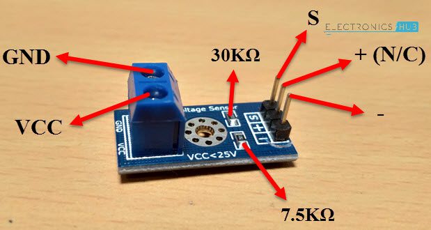
Below table shows the different step sizes for different reference voltages. In the above circuit diagram, pin9 (Vref/2) is left open so that input voltage span can be 0 to 5V. Step size = Vref/(2 pow(n)) Where n is resolution. For ADC0804 the resolution n=8. The digital output can be calculated using the formulae Dout = Vin/stepsize. Vin – analog input voltage For example, let the analog input voltage is 4V, then the digital output is Dout=4/19.53mV=204. #define dat P2 val=dat0.02; val1=val100; temp=(((val1/100)%10)+48); display(temp); display(‘.’); temp=(((val1/10)%10)+48); display(temp); temp=((val1%10)+48); display(temp); Voltage Sensor The voltage sensor module is a simple voltage divider network that increases the analog input range of the ADC to about 25V.
Code
How Digital Voltmeter Circuit Works using 8051 Microcontroller?
Digital Voltmeter Circuit Applications
This system is used to measure the voltage in low voltage applications. Used to measure the toy batteries. We can measure the physical quantities like temperature, humidity, gas etc. using this system with a little modification.
Digital Voltmeter Circuit Limitations
The input analog voltage range should be 0 to 5V. Using this system we can measure only one analog input value at a time.
Digital Voltmeter Circuit using ICL7107
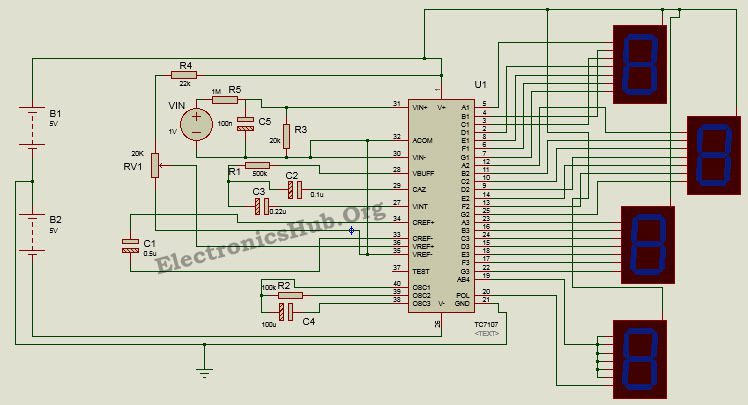
Voltmeter can also be designed without using any microcontroller.Here is the circuit of voltmeter using L7017 IC Here we design a analog to digital converter working as a digital voltmeter using a low power three and half digit A/D converter ICL7107 having internal 7 segment decoders, display drivers, a reference and a clock. An advantage is this IC can directly drive non multiplexed seven segment display without any external decoding circuitry. The circuit can measure voltage in the range of 200mV to 2V with an interval of 0.001V.
Principle Behind the Circuit
This circuit is based on the principle of using ICL7107 as an analog to digital converter. The whole operation is divided into two phases- Analog to digital conversion and decoding. Analog to digital conversion is done using the process of integrating and reference integrating. In other words, the input signal is first integrated to bring the output of integrator to ramp signal and an opposite polarity reference voltage is then integrated to bring the output of integrator back to zero. The resultant digital code obtained is then decoded using to display decoders to drive the display unit.
Digital Voltmeter Circuit Diagram using ICL7107
How Design Digital Voltmeter Circuit?
Designing the circuit requires appropriate selection of the components as given below:
How to Operate Digital Voltmeter Circuit?
The IC is powered by a dual supply of +/- 5V. Once the circuit is powered, the reference signal is set by adjusting the reference resistor. The reference voltage needs to be about half of the input voltage. The oscillating components – resistor and capacitor determine the oscillating or clock frequency of the device. The reference capacitor is charged to the reference voltage. A feedback loop is then closed to charge the auto zero capacitor such that is compensates for any fluctuations in voltages. Later the converter integrates the differential voltage at the input for a fixed time such that output of the integrator is a ramp signal. A known reference voltage is then applied to the input of integrator and is allowed to ramp till the output of integrator becomes zero. The time taken for the output to return back to zero is proportional to the input signal and the digital reading is given as: Display Count = (Vin/Vref)*1000. The next process involves decoding the digital count to produce a seven segment compatible signal so as to drive the displays. The digital output is then displayed on the multiplexed 7-segment display.
Applications of Digital Voltmeter Circuit
Limitations of Digital Voltmeter Circuit
Thank u please do reply ASAP. Comment * Name * Email * Website
Δ
![]()
![]()
![]()
![]()
![]()

