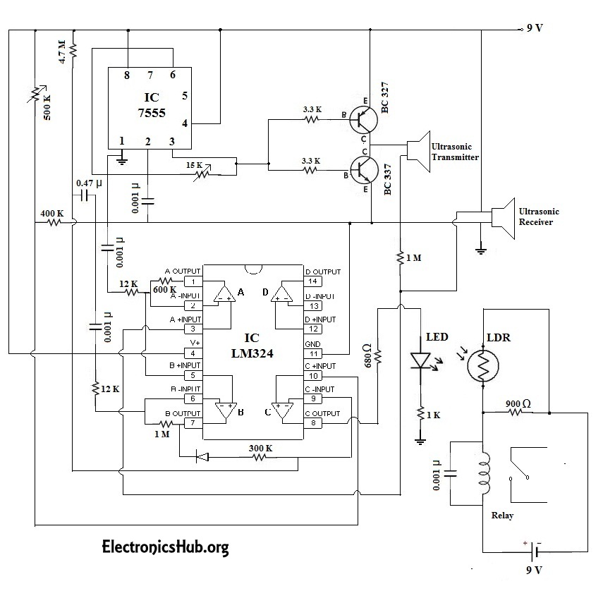
Circuit Diagram of Automatic Door Bell Using Object Detection:
This circuit operates using a pair of ultrasonic transmitter and receiver modules which are used to detect the person and then if the person is detected, the door bell is automatically turned ON when the person is in-front of the door. The ultrasonic transmitter operates at a frequency of about 40 Kilo-Hertz. That means it continuously transmits the ultrasonic waves of about 40KHz. The power supply should be moderate such that the range of the transmitter is only about one or two meters. If the transmitting power is less than one meter, then there is a chance that the person who is one meter away is not detected. Also, if the range is set to be very large, then it may lead to false triggering, meaning that, the objects far away from our door are considered as the visitors and the alarm rings. This can be a nuisance for us if the alarm rings for every object or person far away. So, to avoid both the problems, the transmitting power is kept to an optimum level. The ultrasonic receiver module receives the power at the frequency same as that of the transmitter’s so that noise will be eliminated and we get less false triggering. The sensitivity of the receiver can be tuned by using the 500K-ohm variable resistor arranged as a pot in the circuit. By tuning this properly, we can achieve the desired results. The output of our circuit is given to a buzzer circuit which acts as a doorbell in our case. The receiver in this circuit uses IC LM324 which is internally has four op-amps. Out of the four op-amps, we are using only four of them and leaving the other one unused as it is not much required in our case. The three op-amps are used in cascaded arrangement to provide high gain as well as noise free output. An opto coupler is used at the output to avoid any interaction between our circuit and the door bell. Assemble the circuit on a PCB as compactly as possible and then attach it to your main door. Thats it! You may provide a power supply using a 9V DC adapter with filtered and regulated output. If the 9V adapter with regulated output is not available, then we recommend you to use a 12V unregulated DC adapter with 7809 voltage regulator. I’m really happy to read this project and also interested in this product. I need your help please. Thank you I understand the “buzzer” circuit is separate, to keep the values steady in the original circuit. But if the relay itself is being used as a buzzer, it’s not going to be very audible. And this is also probably why people are asking where is the buzzer. Can the buzzer relay be connected to a sound chime to act as a push button start? From my little search online, it seems this is the ONLY doorbell of it’s type with object detection. So your help would be appreciated. Thanks in advance. Thank you. thanks for your efforts, but I hope you check it again. Comment * Name * Email * Website
Δ
![]()
![]()
![]()
![]()
![]()

